Magstripe emulation specification
Magstripe emulation is a very simple read-only interface that makes a SmartCard reader emulate the bitstream that a magstripe card reader would produce when a magnetic card is being pulled through its slot. This emulation makes a SmartCard reader compatible with legacy controllers that use the Omron interface originally designed for magstripe card readers.
Encoding of data on magnetic cards is described in the standard ISO/IEC 7811-2. This page deals with the parts relevant for the emulation mode.
Supported hardware
Please refer to this host interface overview.
Operation mode
Magstripe emulation requires readers to run in Autoread mode. All other operation modes are not supported.
Supported tracks
Magnetic stripes contain up to 4 tracks with different encoding:
- Track 1: Read-only track with 6-bit alphanumeric encoding
- Track 2: Read-only track with 4-bit numeric encoding
- Track 3: Read-/write track with 4-bit numeric encoding
Currently, BALTECH readers support track 1 and 2. For more details, see chapter Character encoding.
Supported wires
The interface consists of 3 wires controlled by the reader:
- Clock signal (MAG_C)
- Data signal (MAG_D)
- Card Load signal (MAG_CLS)
Currently, BALTECH readers support MAG_C and MAG_D.
(MAG_CLS only signals that a card is "inserted" and is
thus not really necessary for receiving frames via the interface.)
Timing
Frame transmission
The transmission of a frame works as shown in the following diagram. The numbered events are explained below.
- In basic state, both MAG_C and MAG_D are held high.
When a card enters the reader's antenna field, MAG_C stays high for another 10 ms. - MAG_C transmits 16 clock impulses before the start of the data transmission.
This is to synchronize the receiver. - MAG_D starts data transmission.
- MAG_C transmits 16 clock impulses after dater transmission.
- MAG_C stays low for another 30 ms.
- Transmission is completed.
Both MAG_C and MAG_D are switched back to high.
Bit transmission
With 1 pulse of MAG_C, 1 bit is transmitted via MAG_D.
1 pulse of MAG_C takes between 400 and 700 µs; 2/3 are high level, 1/3 is low level.
Data is transmitted during the falling edge.
A logical "1" is signaled by a low level on MAG_D, a logical "0" by a high level.
Enable magstripe emulation
Magstripe emulation needs to be enabled via the reader configuration. A respective configuration component is currently not included in ConfigEditor, but can be provided on request.
Using the host interface component, you can also change the character encoding if needed (see next chapter).
Character encoding
As mentioned in the overview of supported tracks, 2 encoding options are supported:
- 6-bit alphanumeric
- 4-bit numeric
In both cases, data is encoded LSB first, i.e. the least significant bit is transmitted first. The parity bit is always transmitted last.
Configuration value
The following configuration value defines which encoding to use:
- Configuration value: Encoding
- Default: 6-bit alphanumeric
Character mapping for 6-bit alphanumeric encoding
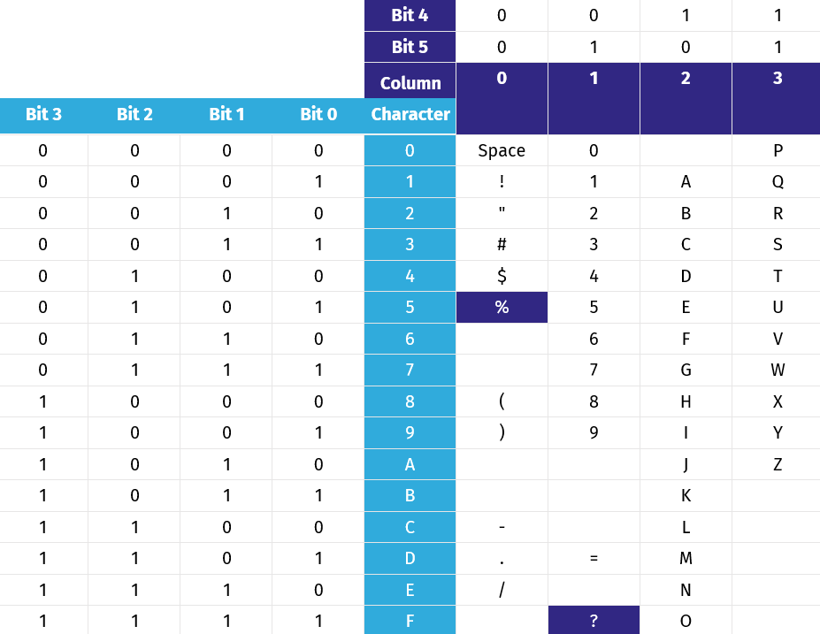
When 6-bit alphanumeric encoding is enabled, characters are mapped as follows:

The empty cells represent special control characters which are only needed for reading magnetic stripes but will never be transmitted by BALTECH readers. The character "%" is used as the start character, the character "?" is used as the stop character.
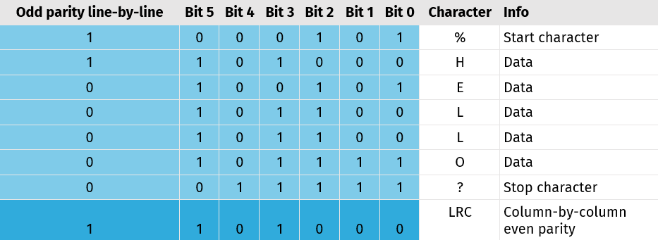
After the stop character, an LRC (longitudinal redundancy check) character is transmitted. It consists of even parity bits over the columns. Over the odd parity bits, no LRC is calculated, but the LRC contains an odd parity bit, too.
Example:

Character mapping for 4-bit numeric encoding
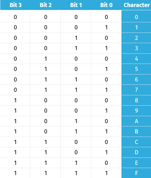
When 4-bit numeric encoding is enabled, characters are mapped as follows. This is equivalent to the left part of the mapping table for 6-bit alphanumeric encoding.

The character "B" is used as the start character, the character "F" is used as the stop character.
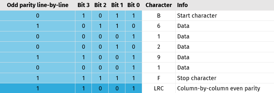
After the stop character, an LRC character is transmitted as described for 6-bit alphanumeric encoding.
Example:
