ACCESS200 hardware specification
Visit our website for a product overview, downloads, and ordering.
Mechanical
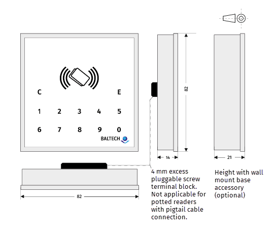
Dimensions in mm. Tolerance +/- 1 mm. Drawing not to scale.
| Mechanical | |
|---|---|
| Dimensions | 82 x 82 x 14 mm (x 21 mm with optional wall mount base) |
| Weight indoor version (incl. standard base and front sticker) |
60 g net 90 g incl. packaging and 2 extra front stickers |
| Weight potted IP55 outdoor version (incl. standard base, front sticker, and 1.8 m pigtail cable) |
175 g net 220 g incl. packaging and 2 extra front stickers |
| Housing material | Translucent PMMA Altuglas, UV-resistant |
| Front sticker | Automotive grade high-quality durable sticker White/silver/anthracite included; customizable |
Power supply
J8 pluggable cage clamp/pigtail cable
The standard way of operating ACCESS200 is via the J8 pluggable cage clamp (unpotted readers) or pigtail cable (potted readers).
Observe the critical voltage drop
When the reader switches on its antenna field, a steep rise of supply current occurs. If power supply or wiring gauge/length is inadequate, this rise may cause short voltage drops that may result in a power-on reset of the reader. To avoid this, please check the wiring gauge and characteristics of the power supply used.
The critical voltage drop is below 7 VDC.
| Power supply via J8 cage clamp/pigtail cable | ||
|---|---|---|
| Supply voltage | 7...30 VDC | ripple 200 mV max |
| I max. supply current @ 7 V | 300 mA | max 1 |
| I max. supply current @ 12 V | 165 mA | max |
| I max. supply current @ 30 V | 80 mA | max |
| I typ. supply current @ 7 V - firmware 1100 v2.10 and above | 110 mA | typ 2 |
| I typ. supply current @ 7 V - firmware 1100 below v2.10 | 160 mA | typ |
| I typ. supply current @ 12 V - firmware 1100 v2.10 and above | 65 mA | typ |
| I typ. supply current @ 12 V - firmware 1100 below v2.10 | 95 mA | typ |
| I typ. supply current @ 30 V - firmware 1100 v2.10 and above | 30 mA | typ |
| I typ. supply current @ 30 V - firmware 1100 below v2.10 | 40 mA | typ |
| I min, sleep modes | on request |
J4 USB connector
Unpotted ACCESS200 readers have a USB connector as a maintenance interface; however, it is also possible to operate readers permanently via USB and power them by USB supply. Critical voltage drops as for the J8 cage clamp or the pigtail cable do not apply here.
In case readers are powered by USB supply, please make sure that supply at J8 is not connected.
| Power supply via J4 USB connector | ||
|---|---|---|
| Supply VDD, VBUS @ USB connector | 4.6...5.5 VDC | ripple 50 mV max. |
| I max. supply current | 450 mA | max 1 |
| I typ. supply current - firmware 1100 below v2.10 | 210 mA | typ 2 |
| I typ. supply current - firmware 1100 v2.10 and above | 150 mA | typ |
| I min, sleep modes | on request |
Average power consumption
The following table lists the average power consumption3 of common reader models.
| Reader model | Autoread all UIDS (factory settings) | Autoread MIFARE DESFire UID |
|---|---|---|
| 10097-611 | ||
| 5 V - firmware 1100 v2.10 and above | 121.1 mA | 82.1 mA |
| 5 V - firmware 1100 below v2.10 | 121.1 mA | 190.7 mA |
| 12 V - firmware 1100 v2.10 and above | 50.5 mA | 34.2 mA |
| 12 V - firmware 1100 below v2.10 | 50.5 mA | 79.5 mA |
| 10119-811 | ||
| 5 V - firmware 1100 v2.10 and above | 128.1 mA | 87.8 mA |
| 5 V - firmware 1100 below v2.10 | 128.1 mA | 197.6 mA |
| 12 V - firmware 1100 v2.10 and above | 53.4 mA | 36.6 mA |
| 12 V - firmware 1100 below v2.10 | 53.4 mA | 82.3 mA |
User interface
| User interface | ||
|---|---|---|
| LED | 4x RGB LEDs Red/Green/Blue/+Mix | Configurable color and intensity, left/right split |
| Beeper | 2700 +/- 300 Hz | |
| Relay | 30 V 1 A |
Environmental
| Environmental | ||
|---|---|---|
| Operating temperature | -40...+60°C (-25...+60°C for 10119 product line) |
Wider temperature range on request |
| Operating humidity (relative) | 5...90% | non-condensing |
| Storage humidity (relative) | 5...90% | non-condensing |
| Environmental rating | IP55 | Potted versions, article#:10097-xxx-03, -04 10119-xxx-03, -04 |
| MTBF | 100,000 h |
RFID interface
| RFID interface | ||
|---|---|---|
| 13.56 MHz | ISO 14443 A/B | 106 kbit/s (optional 848) |
| ISO 15693 | 26 kbit/s | |
| 125 kHz | ASK, FSK, PSK | Modulation types |
| Mobile ID/Bluetooth Low Energy 4.2 | Read range 0.2...15 m, adjustable; BALTECH protocol based on Bluetooth Low Energy for BALTECH Mobile ID; low-level access for the development of custom applications on request | |
| RFID scan duration | Sequential processing | HF = 100 ms LF = 350 ms Multifreq. = 450 ms |
RFID read range
| RFID read range | |
|---|---|
| 13.56 MHz | 15...80 mm typ. NFC optimized for key fob compatibility and metal mounting insensitivity |
| 125 kHz | 20...80 mm typ. |
| Bluetooth Low Energy 4.2 | 0.2...15 m, adjustable |
RFID field strength
| RFID field strength | |||
|---|---|---|---|
| 13.56 MHz | ISO 14443, NFC | Hmin = 1.5 A/m | 15 mm typ. |
| ISO 15693, NFC | Hmin = 0.15 A/m | 70 mm typ. | |
| 125 kHz | No standard available |
Connector and pins
Unpotted/indoor readers
Unpotted/indoor reader rear view
J8 pluggable cage clamp
| Pin # | Signal/funct. | Functional description | Signal spec. | Protection circuitry |
|---|---|---|---|---|
| J8-1 | GND | Power & Signal GND/0V | 0 VDC | |
| J8-2 | +Vin | Power Supply | 7...30VDC | 30 V Supr.&polyfuse |
| J8-3 | WIE_D0/RS485A | Wiegand Data OUT/RS485 | 0...5 V | +12/-8 V Suppressor |
| J8-4 | WIE_D1/RS485B | Wiegand Data OUT/RS485 | 0...5 V | +12/-8 V Suppressor |
| J8-5 | INPUT_0 | Wiegand LED input /general I/O | 0...5 V | 5.6 V Suppressor |
| J8-6 | INPUT_1 | Wiegand LED input /general I/O | 0...5 V | 5.6 V Suppressor |
| J8-7 | REL_WC | Relay working contact | +/- 30V 1A | |
| J8-8 | REL_NO | Relay normal open | +/- 30V 1A | |
| J8-9 | REL_NC | Relay normal closed | +/- 30V 1A |
J4 USB connector
USB Molex PicoBlade 53261-0471
This is the maintenance interface for unpotted readers; however, it is also possible to operate readers permanently via USB and power them by USB supply.
| Pin # | Signal/funct. | Functional description | Signal spec. | Protection circuitry |
|---|---|---|---|---|
| J4-1 | +VUSB (red) | Power Supply USB | 4.6...5.5 VDC | Z-Diode 5.6 V low power |
| J4-2 | D- (white) | USB Data - | 0...3.3 V | Suppressor Diode 4V |
| J4-3 | D+ (green) | USB Data + | 0...3.3 V | Suppressor Diode 4V |
| J4-4 | GND | Power Supply -/Power&Data GND | 0 V |
Potted/outdoor readers
Pigtail cable connection/Molex Pico-SPOX (potted/outdoor versions) stranded, AWG26
| Color | Connector pin# | Signal/funct. | Functional description | Signal spec. | Protection circuitry |
|---|---|---|---|---|---|
| White/Orange | 1 | WIE_D0/RS485A | Wiegand Data OUT/RS485 | 0...5 V | +12/-8V Suppressor |
| Orange | 2 | WIE_D1/RS485B | Wiegand Data OUT/RS485 | 0...5 V | +12/-8V Suppressor |
| White/Green | 3 | INPUT_0 | Wiegand LED in general I/O | 0...5 V | 5.6 V Suppressor |
| Green | 4 | INPUT_1 | Wiegand LED in general I/O | 0...5 V | 5.6V Suppressor |
| Red/White | 5 | USB Data - | USB | 0...3.3 V | 4V Suppressor |
| Black/White | 6 | USB Data + | USB | 0...3.3 V | 4V Suppressor |
| Red or White/Grey | 7 | +VIN | Power Supply | 7...30 VDC | 30 V Supr.&polyfuse |
| Black or Grey | 8 | GND | Power & Signal GND | 0 VDC | |
| White/Blue | 9 | GND | USB GND (reserved for USB maintenance interface) | 0 VDC | |
| Blue | 10 | REL_WC | Relay working contact | +/- 30V 1A | |
| White/Brown | 11 | REL_NO | Relay normal open | +/- 30V 1A | |
| Brown | 12 | REL_NC | Relay normal closed | +/- 30V 1A |
Host interfaces
Here's an overview of the host interfaces supported by ACCESS200. If you develop your own application, please also see the overview of host protocols available per interface.
Out of the box
| Connector # | Interface | Specifics |
|---|---|---|
| J4 | USB |
|
| J8 | RS-485 (OSDP V1 and V2, custom protocols) |
|
| Wiegand |
|
On request
| Interface | Specifics |
|---|---|
| RS-232/UART |
|
| Magstripe emulation |