Technical data ID-engine Z Module/BRICK
Mechanical
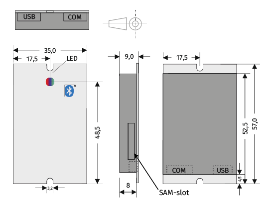
ID-engine Z Module
| Mechanical | |
|---|---|
| Dimensions | 57 (48) x 35 x 9 mm |
| Weight | 11 g |
| Housing material | Makrolon translucent |
Download 3D files (STP format) with 1 and 2 connector break-outs
ID-engine Z BRICK
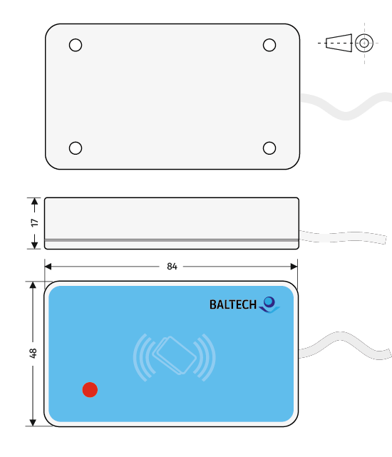
Dimensions in mm. Tolerance +/- 1 mm. Drawing not to scale. Mounting holes centered, distance 64x34 mm, 4 mm diameter
| Mechanical | |
|---|---|
| Dimensions | 84 x 48 x 17 mm fixed cable 1.8 m |
| Weight | 100 g net (150 g incl. packaging) |
| Housing material | ABS/PC |
Power supply
When the reader switches on its antenna field, a steep rise of supply current occurs. If power supply or wiring gauge/length is inadequate, this rise may cause short voltage drops that may result in a power-on reset of the reader. To avoid this, please check the wiring gauge and characteristics of the power supply used.
The critical voltage drop is below 4.6 VDC.
| Power supply | ||
|---|---|---|
| Supply VDD, VBUS @ module | 4.6...5.5 VDC | ripple 50 mV max. |
| Supply VDD, VBUS @ USB or RS-232/UART cable end (BRICK) | 4.75...5.5 VDC | ripple 50 mV max. |
| I max. supply current | 300 mA | max |
| I typ. supply current - firmware 1100 v2.10 and above | 120...140 mA | typ1 |
| I typ. supply current - firmware 1100 below v2.10 | 150...200 mA | typ |
| I with HF ON only | 210 mA | typ |
| I with LF ON only | 100 mA | typ |
| +I @Bluetooth RX/TX active | 3/10 mA | typ |
| +I @Beeper 4kHz ON | 25 mA | typ |
| + I @ per LED-color ON | 15 mA | typ |
| I RFID OFF, LED & Beeper OFF, idle | 40 mA | typ |
| I sleep modes | on request |
Average power consumption
The following table lists the average power consumption2 of common reader models.
| Reader model | Autoread all UIDs (factory settings) | Autoread MIFARE DESFire UID |
|---|---|---|
| 10115-610 | ||
| firmware 1100 v2.10 and above | 78.5 mA | 38.5 mA |
| firmware 1100 below v2.10 | 83.7 mA | 140.6 mA |
| 12115-610 | ||
| firmware 1100 v2.10 and above | 67.6 mA | 34.9 mA |
| firmware 1100 below v2.10 | 78.1 mA | 118.2 mA |
| 10117-810 | ||
| firmware 1100 v2.10 and above | 84.6 mA | 41.2 mA |
| firmware 1100 below v2.10 | 95.3 mA | 169.9 mA |
| 12117-810 | ||
| firmware 1100 v2.10 and above | 77.2 mA | 37.8 mA |
| firmware 1100 below v2.10 | 90.8 mA | 159.6 mA |
User interface
| User interface | |
|---|---|
| LED | RGB LED Red/Green/Blue/+Mix; configurable color and intensity |
| Beeper | 4000 +/- 300 Hz |
Environmental
| Environmental | ||
|---|---|---|
| Operating temperature | -40...+60°C (-25...+60°C for 10117 product line) |
Wider temperature range on request |
| Storage temperature boxed | -40...+70 °C | |
| Operating humidity (relative) | 5...90% | Non-condensing |
| Storage humidity (relative) | 5...90% | Non-condensing |
| MTBF | 200,000 h |
RFID interface
| RFID interface | ||
|---|---|---|
| 13.56 MHz | ISO 14443 A, B | 106...848 kbit/s |
| ISO 15693 | 26 kbit/s | |
| 125 kHz | ASK, FSK, PSK | Modulation types |
| Mobile ID/Bluetooth Low Energy 4.2 | Read range 0.2...15 m, adjustable; BALTECH protocol based on Bluetooth Low Energy for BALTECH Mobile ID; low-level access for the development of custom applications on request | |
| RFID scan duration | Seq. processing | HF = 100 ms LF = 350 ms Multifreq. = 450 ms |
RFID read range
| RFID read range | |
|---|---|
| 13.56 MHz | 20...80 mm typ. NFC optimized for key fob compatibility and metal mounting insensitivity |
| 125 kHz | 20...80 mm typ. |
| Bluetooth Low Energy 4.2 | 0.2...15 m, adjustable |
RFID field strength
| RFID field strength | |||
|---|---|---|---|
| 13.56 MHz | ISO 14443, NFC | Hmin = 1.5 A/m | 20 mm typ. |
| ISO 15693, NFC | Hmin = 0.15 A/m | 80 mm typ. | |
| 125 kHz | No standard available |
Reading distance for common card types
| Reading distance | |||
|---|---|---|---|
| 10115-xxx-yy | 10117-xxx-yy | ||
| MIFARE Classic 4k | 32 byte read/write | 45 mm | 45 mm |
| MIFARE DESFire EV1 key-fob | 150 byte read/write AES | 20 mm | 20 mm |
| DESFire EV2 card | 150 byte read/write AES | 46 mm | 45 mm |
Connector and pins (ID-engine Z Module only)
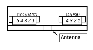
J4 - USB, Molex PicoBlade 53261-0471
| Pin # | Signal/funct. | Functional description | Signal spec. | ID-engine module circuitry |
|---|---|---|---|---|
| J4-1 | +VUSB (red) | Power supply USB | 4.6...5.5 VDC | Z-Diode 5.6V low power |
| J4-2 | D- (white) | USB Data - | 0...3.3 V | Suppressor diode 4V |
| J4-3 | D+ (green) | USB Data + | 0...3.3 V | Suppressor diode 4V |
| J4-4 | GND | Power supply -/Power&Data GND | 0 V |
J102 (optional) - UART, Molex PicoBlade 53261-0571
| Pin # | Signal/funct. | Functional description | Signal spec. | ID-engine module circuitry |
|---|---|---|---|---|
| J102-1 | +5V | Power supply + | 4.6...5.5 VDC | Suppressor diode 5.6 V |
| J102-2 | 0 V / GND | Power supply -/Power&Data GND | 0 V | 0V |
| J102-3 | RX1 | ID-engine data receive | +/- 12 V | RS232 transceiver IC (RX) |
| J102-4 | TX1 | ID-engine data send | +/- 12 V | 330R series-R, RS232 IC (TX) |
| J102-5 | Do not connect | Suppressor diode 5 V | ||
| Alternatively | ||||
| J102-1 | +5V | Power supply + | 4.6...5.5 VDC | Suppressor diode 5,6 V |
| J102-2 | 0 V / GND | Power supply -/Power&Data GND | 0 V | 0 V |
| J102-3 | RX1 D1 DATA GPIO |
UART data receive Wiegand Data OUT Magstripe Data GPIO |
0...5 V | 330R ser., 5 V Z-D, 47k to +5 V |
| J102-4 | TX1 D0 CLK GPIO |
UART data send Wiegand Data OUT Magstripe Clock GPIO |
0...5 V | 330R ser., 5 V Z-D, 47k to +5 V |
| J102-5 | GPIO | Depends on configuration | 0....5 V CMOS | Suppressor diode 5 V, 470R to +5 V |
Special custom interface on request, flat ribbon pigtail cable located between J4 and J102
| Pin # | Signal/funct. | Functional description | Signal spec. | ID-engine module circuitry |
|---|---|---|---|---|
| J3-1 | TX2 | ID-engine data send | 0...5 V | 470R pullup to +5 V |
| J3-2 | RX2 | ID-engine data receive | 0...5 V | 47k pullup to +5 V |
| J3-3 | SCL | IIC interface, direct uC | 3.3 V 10 mA max | Suppressor diode 5.6 V; no resistor |
| J3-4 | SDA | IIC interface, direct uC | 3.3 V 10 mA max | Suppressor diode 5.6 V; no resistor |
| J3-5 | +3V3 | 3.3 V output | 20 mA max | no protection |
| J3-6 | 0 V/GND | Power supply -/Power&Data GND | 0 V |
ID0 slot SAM connector ISO7816
| Signal/funct. | Functional description | Signal spec. |
|---|---|---|
| VDD | Power supply | 3.3 V |
| Ivdd | Max. current continuous | 50 mA |
| Max. current peak (10ms) | 100 mA |
Qualified for NXP MIFARE SAM-AV2, -AV3 and HID iCLASS SE Processor. Please contact us for support of further SAMs.
Additional information on connectors: Molex PicoBlade 53261 mates with Molex 51021 housing plus contacts:
- #50079 for wires AWG26-28
- #50058 for wires AWG28-32
Host interfaces
Here's an overview of the host interfaces supported by ID-engine Z. If you develop your own application, please also see the overview of host protocols available per interface.
| Connector # (Z Module only) |
Physical interface | Details |
|---|---|---|
| J4 | USB | 2.0 full speed |
| J102 (optional) | UART |
2 standard hardware variants available:
On request:
|
| I2C (on request) |
- Polling ON, LED single color: ON ↩
- Red LED on, no card presented ↩
- ID-engine Z configured for Wiegand outputs CMOS-level signals rather than actively driven signals. I/O wires to control reader LEDs and other hardware components currently not supported. Support for 1 I/O wire can be implemented on request. ↩