Operating volume
The operating volume is the distance range around the reader antenna within which a card can be read.
General principles of operation
Contactless readers create an alternating magnetic field to enable communication with a transponder (e.g. a card). This magnetic field is generated by two coils built into the reader, also referred to as antennas. Reading data works best if the transponder is held parallel to the reader surface and is placed right at the center of the reader antennas. The center is indicated by a symbol on the reader front sticker.
Limited range of key fobs
Small key fobs have a lower range than larger transponders (e.g. cards). Thus, it's especially important to place key fobs closely to the center of the reader antennas.
Influencing factors
The operating volume depends on the following:
- Reader type (ID-engine Z or ACCESS200)
- Card type
- Reader orientation: The operation volume along the reader antenna's X axis (i.e. long edge) is different from the reader antenna's Y axis (i.e. short edge).
Potential connection loss
Note the side lobes of the operating volume at the reader edges. They may cause the card to be read several times if it enters the antenna field close to the reader surface. In between the side lobes and the main operating volume, connection to the reader may be completely lost.
Effects:
- Read results may be transmitted several times to the host system.
- Reading the card may fail completely if the operation can't be completed before the connection is lost. In this case, an error will be thrown in the host system.
Recommendations
- For integrators: If you install the reader below the surface, e.g. of a device, make sure you keep proper distance between the reader module and the surface.
- For developers: If you use low-level commands to interact with the cards directly, make sure you implement retry mechanisms and adequate error handling. Autoread and VHL already have these mechanisms in place.
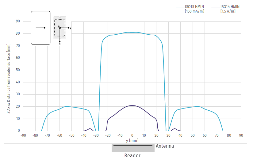
Volume diagrams
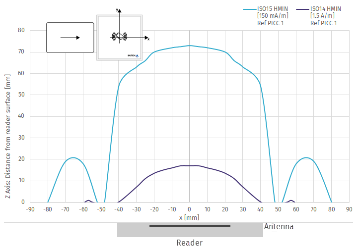
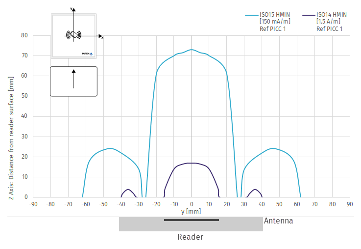
The following diagrams show the exact operating volumes per reader type, card type, and direction of movement.
- Vertical axis represents the distance between card and reader surface (in parallel orientation)
- Horizontal axis represents the reader antenna's X axis or Y axis respectively
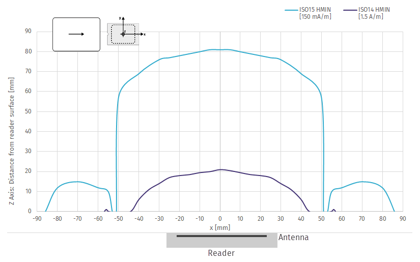
ID-engine ZM
Model 10115-610
Card moving along the reader's Y axis (X=0)
Card moving along the reader's X axis (Y=0)
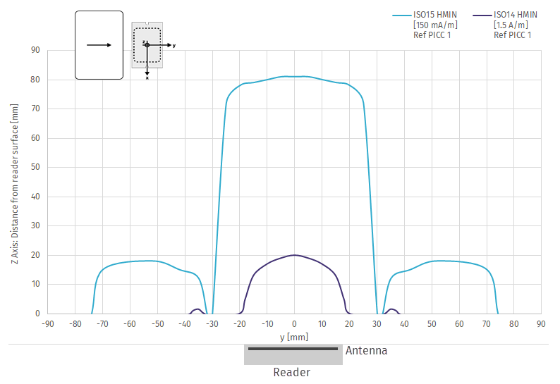
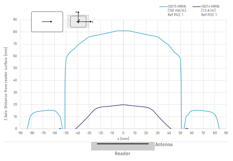
Model 10117-810
Card moving along the reader's Y axis (X=0)
Card moving along the reader's X axis (Y=0)
ACCESS200
Model 10097-611-01
Card moving along the reader's Y axis (X=0)
Card moving along the reader's X axis (Y=0)
Model 10119-801-04 (with keypad)
Card moving along the reader's Y axis (X=0)
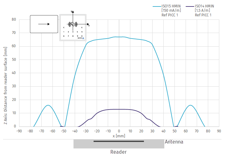
Card moving along the reader's X axis (Y=0)
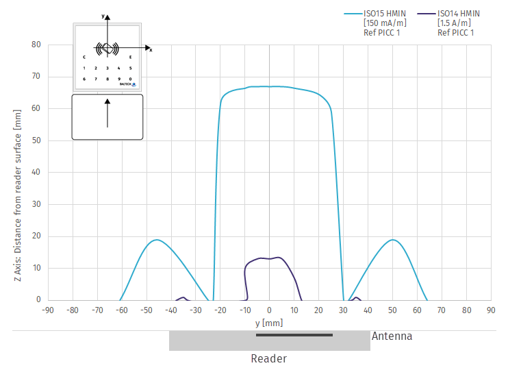
The unusual shape of the 1.5 A/m diagram (purple line) is due to keypad pcb inside ACCESS200 which is shielding the card close to the surface.