ACCESS200 installation guide for configuration via ConfigCard or Wireless Upload (NFC)
For configuration via Wired Upload (USB) or preconfigured readers, use the separate installation guide.
Equipment
- Printed installation quick guide
-
ACCESS200 reader including base part
Check dimensions
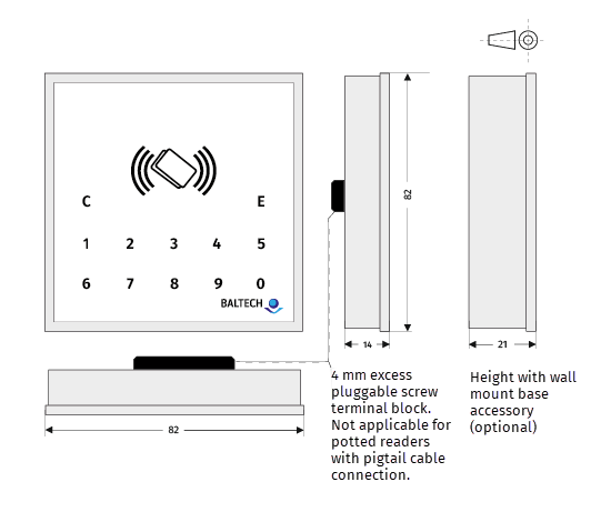
Dimensions in mm. Tolerance +/- 1 mm. Drawing not to scale.
For more technical data, please see our hardware specification. -
3mm diameter countersunk head screws (to fix the base part)
- Project card (to test reader and configuration)
-
Optional: AdrCard (to set bus address), LicenseCard (to deploy Prox license), View in online shop
-
To deploy the configuration:
- Via ConfigCard:
- A ConfigCard with the configuration stored on it
- Alternatively, technicians can create their own ConfigCards on site; see equipment and requirements here
- Via Wireless Upload:
- Via ConfigCard:
Installation
-
Fix base part
- Fix the base part with the 3 mm diameter countersunk head screws.
- Heads must not stand out more than 1 mm from the base surface.
For outdoor keypad readers, make sure you avoid rain interference.
-
Wire reader
Connect the reader to the host system according to the connector and pin specification.- For unpotted readers, you can unplug the clamp J8.
- For potted readers, cut the connector off the pigtail cable, shorten the cable, and strip the wires.
-
Close housing
- For unpotted readers, plug the wired clamp back on the reader.
- Fit the reader on the base.
- If you need to reopen the housing, follow these instructions to avoid damage.
-
Optional: Set bus address
- To enable a bus protocol (by default OSDP), set a bus address on each reader.
-
Optional: Deploy Prox license
- If you want to read HID Prox, Indala, or Keri project cards, and your readers don't have a Prox license yet, deploy a Prox license using BALTECH LicenseCard.
-
Optional: Test reader
- Readers will now read any card's UID (serial number) and transmit it to the host system.
- To test the reader, configure the host system temporarily to accept your project card's UID.
-
Deploy configuration
-
Via ConfigCard:
- If the configuration isn't stored on the ConfigCard yet, create the ConfigCard with BALTECH Uploader.
- With the configuration stored on the ConfigCard, deploy the configuration as described here.
-
Via Wireless Upload:
- Deploy the configuration as described here.
-
-
Test configuration
- Test the configured reader with a project card. The host system must be configured for live operations.